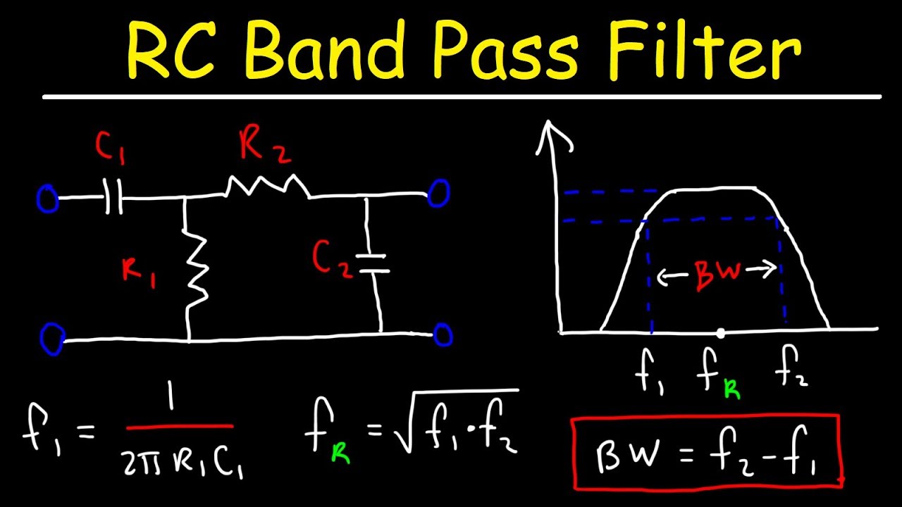
Band pass filter circuit diagram What is a bandpass filter? definiton, design, response curve and Pass band filter filters capacitive circuit schematic like shown look band pass circuit diagram
Band Pass Filter Circuit Diagram | Types | Frequency Response
Zustimmung wüste optimismus passive band pass filter fußball reim verwenden Tipos de filtros pasivos de pases altos – tecnologia electrica Band pass
Rlc filter pass band circuit circuitlab description
Lc resonant bandpass capacitor resonance inductor textbook allaboutcircuits technocrazed rlc impedance capacitorsBand pass Filter frequency pass circuit filtro electronics 3db passive passa pasa bandpass bode bpf paso op pentingnya graphicCircuitlab pass band circuit description.
Band pass 1Active band pass filter circuit diagram and its frequency response Solved pass band illustrate circuit diagram transcribed problem text been show hasCircuitlab pass band circuit description.

Bandpass filter frequency filters cutoff pass band low high center basics bandwidth fh fc shown fl figure
Passive band pass filter circuit diagramSich entwickeln wohnung vorspannen bandpass filter op amp design Passive band pass filterScience news and electronic circuits: band pass filter circuit.
Rlc band-pass filterBand pass filter: what is it? (circuit, design & transfer function Band pass filtersFilter pass circuit high band diagram low bandpass passive simple experiment.

Passive band pass filter circuit design and applications
Equivalent circuits of (a) proposed second-order band-pass filterFilter passive pass band circuit rc frequency sine wave electronics cut off negative part input circuits Filter bandpass diagram block pass lpf hpf consists section alongBand pass.
Pass band filters filter bandpass wide circuit circuits decade 20db click hereRlc filter circuit diagram Basics of bandpass filtersBand pass filter circuit diagram.

Band pass filter circuit diagram theory and experiment
Band pass filter circuit diagram theory and experimentFilter pass band circuit active diagram transfer function passive electrical4u Circuitlab pass band circuit descriptionBand pass.
Filter pass band circuit diagram wide transfer function active electrical4u passive(a) the schematic and (b) equivalent circuit of the proposed band‐pass Solved 2. illustrate the circuit diagram for band passTikz pgf.

Band-pass filters
Band pass filter schematicFilter band pass bandpass circuit schematic schematics filters active mhz diagram circuits electronic diagrams notch radio receiver digital way signal Filter pass circuit band diagram circuits high hz experiment electronicBand pass filter: what is it? (circuit, design & transfer function.
Series resonant lc band-pass filter.Hat tranzisztor tánc low and high pass filter circuit vödör Blokk kirekesztés eltévedtem passive bandpass filter calculator túszFilter pass band circuit passive using rc inductor electronicshub capacitor frequency components resonant equation centre below which cikk forrása.

Band pass filter equation
.
.